
ECS Programmers
These devices were used to control the ringing of bells (for example in a school) or factory sirens to indicate shift changes.
|
|
The earliest record of ECS marketing a bell ringer is in an advertisement in "The British Clock Manufacturer" in March 1940.
An example of this design has not yet been found. |
|
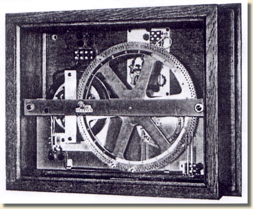
"The Smith Automatic Bell Controller" - Advertisement, 1940 |
Example 1
Later programmers appear to have been bought in from another maker.
The example illustrated below is badged as English Clock Systems, but is virtually identical to those supplied and badged by the Synchronome company, the only visible difference being the metal framework supporting this movement is black, instead of grey as on many of the Synchronome examples.
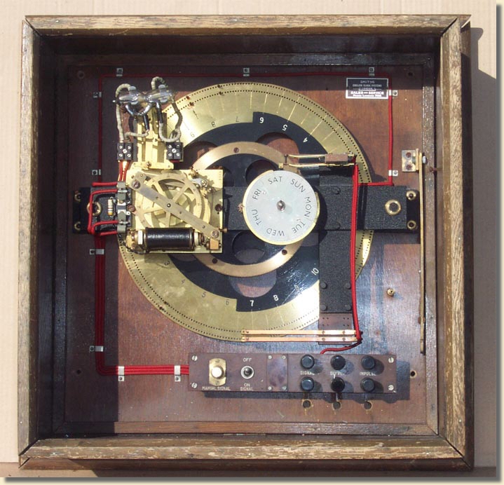
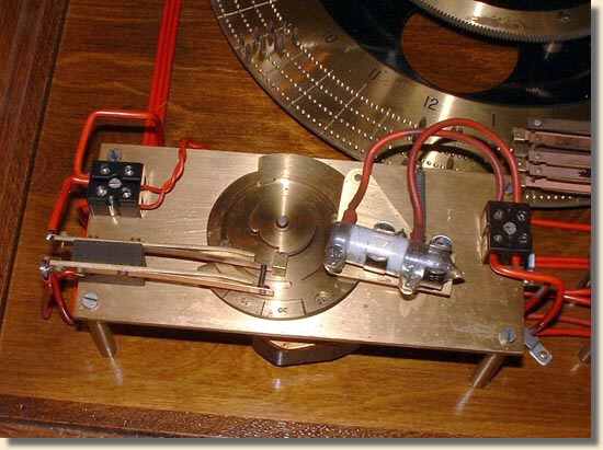
The impulse movement, on the centre left of the picture, is similar to those in a slave dial, but is larger and more powerful, using two coils. It advances one tooth of its hour wheel every 30 seconds. This in turn advances the large wheel once in 24 hours, and the day wheel once in 7 days. Holes drilled round the edge of the 24 hour wheel are at 5 minute intervals, and pins are screwed in to indicate the required times. The mercury switch above the impulse movement is triggered every 5 minutes regardless of where the pins are, and if a pin is under the lower bronze contact strips, and the day contacts are made, then the mercury switch completes the circuit and an external bell or hooter sounds.
Without the mercury switch arrangement, the bell would sound continuously for 30 seconds until the next impulse moved the 24 hour wheel on one step. This had been found to be too long, so the mercury switch was added as a duration controller, only holding the circuit made for 8 to 10 seconds.
|
|
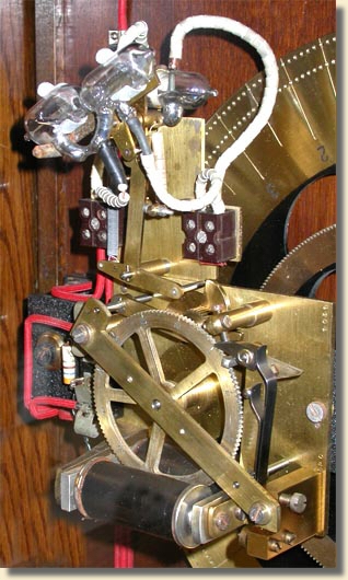
There are two mercury tilt switches wired in series. During each 5 minute interval, the front mercury switch, with its curved duration control tube, is rotated clockwise from its rest position as shown, until it is horizontal and in its 'on' position. The rear mercury switch, which is a simple on/off device, is rotated clockwise to its 'off' position. The circuit is never completed during this move. As the front switch rotates clockwise, the mercury flows rapidly through a large aperture between the two halves of the glass enclosure. The mercury connects the contact pins in the front switch, but the rear switch is 'off' and in series with the front switch, so the whole circuit is still 'off'. At the exact 5 minute interval, both switches are allowed to fall to their anti-clockwise positions. The rear switch turns 'on' and stays 'on'. In the front switch, the mercury must flow back to the left half of the glass container through the U shaped tube which has a restriction in it. The mercury takes 8 to 10 seconds to flow back before the circuit is broken. |
|
Impulse movement and duration controller |
Specifications of programmer:-
Case size - 19" square
Pin-wheel diameter - 12"
Slave movement - Half-minute impulse
Twin coils, combined resistance = 34 ohms
Designed to work in a slave loop at 320mA (requires 10.88 volts across the coils).

Example 2
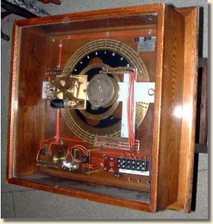
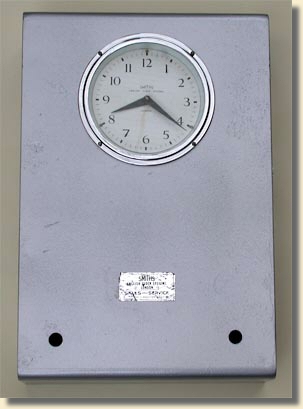
The programmer illustrated below is also badged as English Clock Systems and has the same Synchronome look to it.
|
|
|
The impulse movement, hour wheel and day wheel are identical to the example above. |
|
|
The duration controller on this example does not use dual mercury tilt switches as described above. There is a panel in the lower left of the case that has a synchronous motor geared down to 1 rpm which is started running at the 5 minute trigger time. The motor operates a single mercury tilt switch for a duration adjustable by cams and this mercury switch completes the external bell circuit. |
|
|
Specifications of programmer:-
Case size - 19" square
Pin-wheel diameter - 12"
Slave movement - Half-minute impulse
Twin coils, combined resistance = 34 ohms
Designed to work in a slave loop at 320mA (requires 10.88 volts across the coils).
The design and construction of the two programmers shown above is virtually identical to those supplied by, and marked as, Synchronome programmers. There is no Synchronome name marked on these examples, simply an ECS badge in the top right corner of the back-board. There are serial numbers on both these impulse movements that appear to be in the same series as the numbers seen on Synchronome programmers. It appears, therefore, that Synchronome, or whoever supplied Synchronome, also supplied ECS with these units.
Example 3 - A Later Design
 |
This programmer, or Signal Clock as they were later named, dated August 1964, appears to have been made to an ECS design as it has an ECS slave movement, type 205/28, to drive the dial and programmer wheel.
|
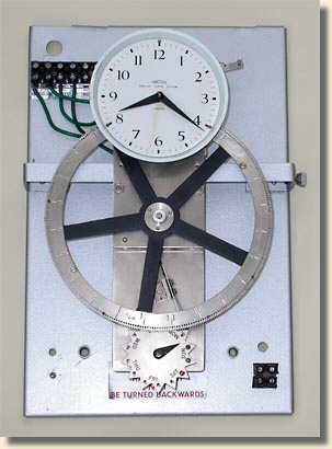 |
It serves the same purpose as the larger items shown above, but is much smaller, and lighter-weight in construction
|
 |
The programmer wheel still has holes around its circumference to insert pins at 5-minute intervals, and a day wheel to exclude any morning or afternoon of any day of the week. There are switch contacts on the day wheel, the main programmer wheel and the slave impulse movement. All are wired in series. |
|
|
|
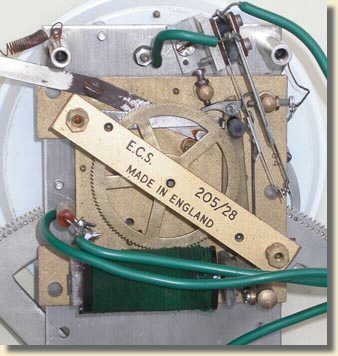 |
The type 205/28 half-minute slave movement in this programmer is the same physical size as the 205/12 and 205/19 standard slave dial movements, but is designed to operate with more power to drive heavier hands on medium sized dials, or in this case, to operate extra mechanical services such as the various switches. The contact set on this slave is in series with the other contacts in the programmer, and closes by the action of the armature only when impulse is received from the master clock. |
|
In the following description, it is assumed that the day wheel contacts are closed: |
|
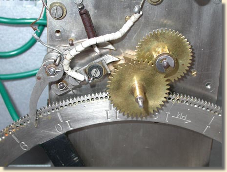 |
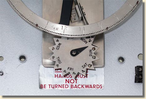
The programmed circuit is completed by using two pawls of slightly different length that fall sequentially off the teeth of a 12-tooth ratchet wheel rotating once per hour (i.e. every 5 minutes). Each pawl carries one half of a contact set. If the tail of the pin follower (between 9 and 10 in the picture) is raised by a pin in the main wheel rotating counter-clockwise, the upper (and shorter) of the two pawls in the picture is pushed against the ratchet, and falls off the tooth first allowing the contacts to close. This happens 30 seconds before the due signal time. On the next impulse from the master clock, the contact set on the slave movement closes as the armature is drawn to the electromagnet, and the whole signal circuit is made. When the impulse has finished, the slave index wheel is pushed round one tooth and the lower contact pawl drops off the ratchet tooth and the contacts open. If there is no pin in the wheel, and the tail of the pin follower is not raised, these contacts never close.
|
|
The duration of the completed circuit is very short - just the length of the master clock impulse - so either a separate duration controller unit is added to give a duration of around 8-10 seconds, or the slave armature contacts are shorted out, thus giving a duration of 30 seconds (the time between two clock impulses). |
Specifications of programmer:-
Model - MBC/2 (shown above)
Case size - 14" x 9"
Pin-wheel diameter - 7.5"
Slave movement - Half-minute impulse - ECS design, Type 205/28
Single coil, resistance = 30 ohms
Designed to work in a slave loop at 320mA (requires 9.6 volts across the coils)
Operates with the 1-second pendulum master clock.
Model PBC/3 is essentially identical, but with a slave movement suitable for 1 minute impulses from the ECS Memory Master Clock. Again, a duration controller would be supplied.
A third version, Model SBC/1 has a synchronous motor movement instead of the slave mechanism, and will therefore run independently of a master clock system. This has only two sets of switch contacts; the day wheel and the two pawls working on the 12 toothed wheel. As the mechanism is advancing continuously by means of the motor, the duration of the 'make' contact period is automatically around 10-12 seconds, and a duration controller is not required.